 11
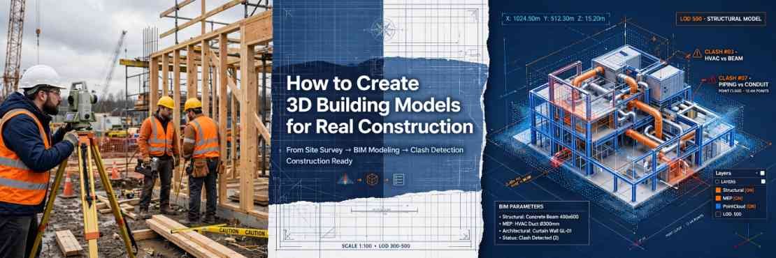
The working method behind how to create 3D building models for an actual job site is not a software question, it is a coordination question. The geometry is the easy part. What kills projects is a model that nobody agreed to, measured against a survey that was never reconciled, and issued to a trades crew that treats it as scenery rather than instruction. A model only earns its cost when it carries a stated level of detail, a named responsible party, and coordinates that survive contact with the field.
This guide walks the full sequence for how to create 3D building models inside a construction context: setting the purpose before touching geometry, capturing existing conditions, choosing the authoring platform, structuring the model for downstream trades, running clash detection, and handing off files that hold up after the designer is gone. It is written for owners, builders, and project managers who need the model to pay for itself, not for people looking to render a pretty picture of a house.
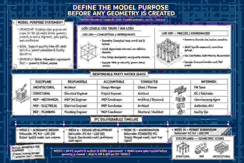
The first decision in how to create 3D building models has nothing to do with a keyboard. It is deciding what question the model has to answer. A model built for a marketing flyer and a model built for MEP coordination are different products with different budgets, and pretending otherwise produces the worst outcome: expensive geometry that satisfies neither use.
The National Institute of Building Sciences has spent years documenting why model handoffs fail between design and construction, and the recurring culprit is scope ambiguity at the front end. Before authoring begins, the team should write down four things: what the model will be used for, who owns each discipline’s content, what level of development each element requires, and what the deliverable file format will be at each project milestone. This sounds like paperwork, and it is, but it is the paperwork that keeps a framing model from being rebuilt three times because the steel detailer used different conventions.
A practical purpose statement for a residential or light commercial job might read: “The model will support permit drawings, framing coordination, and mechanical rough-in routing, authored at LOD 300 for structural and LOD 200 for MEP, delivered as IFC at design development and construction documents.” Once that sentence exists, every subsequent decision about how to create 3D building models gets easier because there is a reference point to argue against.

Modeling a building that does not exist yet is straightforward geometry. Modeling a renovation or an addition on top of an existing structure is where models go wrong, because the author assumes the building is square, plumb, and matches the drawings from 1974. It does not.
There are three accepted capture paths, and the choice depends on scope and tolerance. Total station and manual measurement works for small residential additions where the tolerance is measured in fractions of an inch and the budget will not support scanning. As uav surveying is changing mapping across large sites, photogrammetry from drone or handheld capture offers a fast, affordable option for exteriors and site context, though it struggles with reflective surfaces and tight interior spaces. Laser scanning, either terrestrial or SLAM-based mobile mapping, produces a dense point cloud that can be registered and used as a modeling reference for complex existing conditions.
Whichever method is used, the scan or survey data must be registered to a single project coordinate system before anyone starts modeling. The National Institute of Standards and Technology has published extensive work on dimensional tolerance and interoperability in construction data, and the practical takeaway is simple: a model built on an unregistered point cloud inherits every error in that cloud, then adds modeling error on top. Register first, verify control points in the field, then model.
| Capture Method | Typical Use | Accuracy Range | Best Fit
|
|---|---|---|---|
| Manual measurement and total station | Small additions, single rooms, verification | High precision at measured points, sparse coverage | Residential renovations with tight budgets |
| Photogrammetry | Exterior facades, site context, roofs | Moderate, degrades on reflective or occluded surfaces | Quick context models and marketing geometry |
| Terrestrial laser scanning | Complex interiors, mechanical rooms, historic structures | High, dense point coverage | Renovations where existing conditions are uncertain |
| Mobile SLAM scanning | Large floor plates, occupied buildings | Moderate to high, faster field time | Commercial fit-outs and as-built documentation |
Autodesk Revit remains the default authoring environment for how to create 3D building models in commercial construction, and the reasons are practical rather than ideological: it is what the consultant pool knows, it produces schedules and sheets from the same model, and its interoperability with Navisworks and other coordination tools is mature. Bentley OpenBuildings and Archicad both hold legitimate market positions, and the choice should follow the team’s existing skills rather than a software brochure.
What matters more than the platform is the standards document that sits alongside it. Whether applied to vertical builds or heavy civil construction, that document should define the project base point and shared coordinates, the naming convention for views and sheets, which worksets or categories are reserved for which discipline, and the modeling conventions for walls, slabs, and openings. It should also state what is explicitly out of scope for the model, because the fastest way to inflate a model budget is to let a modeler include furniture, fixtures, and finish detail that nobody on the construction side will ever query.
For teams building their first model, the temptation is to author everything at a high level of development. Resist it. Model at the level the next consumer needs, no further. A framing crew needs accurate member locations and dimensions, not a rendered texture map of the sheathing. A mechanical contractor needs clear routing space and connection points, not a modeled fan blade inside the air handler.
How to create 3D building models that survive transfer to subcontractors depends almost entirely on structural discipline during authoring. The model should be organized by building system: foundations, structural frame, exterior envelope, interior partitions, and each MEP discipline. This separation allows a trade contractor to isolate their scope, take off quantities, and coordinate without loading the entire building into a viewer on a laptop that cannot handle it.
Elements should be modeled as the correct category rather than as generic solids. A wall modeled as a generic mass cannot generate a schedule, cannot be tagged, and cannot participate in a rule-based clash check. A wall modeled as an architectural wall with the correct assembly and thickness can do all three. That single habit, applied consistently, does more for downstream usability than any post-processing effort.
Coordinate systems deserve explicit attention because they are the most common source of silent failure. Every linked model must share the same project base point and survey point. When the structural model and the architectural model disagree on the origin by a few feet, everything appears to clash everywhere, and the coordination meeting becomes a debate about origins rather than a discussion about real conflicts. Set shared coordinates once, publish them, and require every consultant to acquire them from the master file.
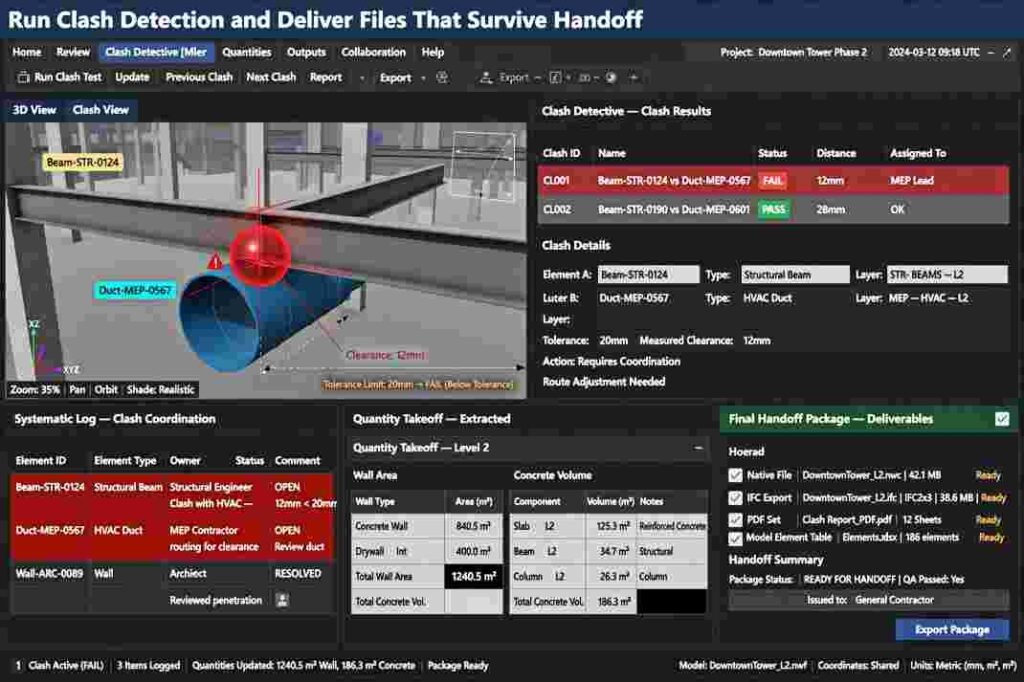
Clash detection is the step where the model starts paying for itself, but only if it is run with a filter rather than a firehose. An unfiltered clash run on a mid-sized commercial building can produce thousands of results, most of which are duplicates, irrelevant, or already resolved. The productive approach is to run targeted tests between specific discipline pairs: structural framing against ductwork, plumbing against structural beams, electrical trays against sprinkler mains.
The National BIM Standard work coordinated through NIBS offers useful guidance on information exchange requirements that map directly to how clash tests should be scoped. The practical workflow is to log each clash with a screenshot, an element ID, an assigned owner, and a due date. Clashes that are accepted as intentional, such as a penetration through a slab that has a sleeve, should be closed with a documented note rather than deleted silently, because the next coordination cycle will surface them again otherwise.
Hard clashes get the attention, but clearance clashes cause more field problems on residential and light commercial work. A duct that fits under a beam with no insulation clearance is a geometry pass and a real failure. Set the clearance tolerances in the clash software to match the actual required working space, not to zero.
The most direct return on modeling effort is the ability to pull quantities straight from the model rather than counting from drawings. How to create 3D building models that support quantity takeoff requires that the model use consistent parameters: correct element categories, consistent type naming, and a shared unit convention across all disciplines. When those conditions hold, a takeoff tool can extract wall area, floor volume, concrete quantity, and framing member counts with traceable results.
Fabrication-level detailing is a separate step and usually a separate model. A steel detailer working in Tekla or a similar platform will produce a fabrication model from the design model, with connection details, bolt holes, and shop-ready geometry. The design model should not attempt to reach that level of detail; it should instead provide a clean, well-named, correctly categorized reference that the detailer can import without cleaning up someone else’s shortcuts.
Two conditions determine whether takeoffs will be trustworthy. First, modelers must not use generic placeholder elements for items they intend to specify later, because those placeholders will either be missed in the takeoff or counted as something they are not. Second, the team must agree on a model state for takeoff purposes, typically issued at a defined milestone with a clear revision tag, so that a quantity extracted in March is not silently compared to a model that changed in April.
Model validation is the discipline of asking whether the model is internally consistent before it leaves the author’s hands. A validation pass should confirm that the shared coordinates are correct, that no elements are floating without hosting, that rooms and spaces are enclosed, that the model is free of duplicate elements at the same location, and that file sizes have not ballooned because of imported CAD clutter that should have been purged.
Automated rule-checking tools can run many of these checks in a batch, and their use is now standard practice on larger projects. The questions worth programming into a rule set include: does every wall have an assigned type and fire rating where required, are all rooms enclosed, do doors and windows host to a wall, and does the model contain any elements outside the project boundary. Catching a hosted-window failure in the model is far cheaper than discovering it when a window is ordered against a rough opening that does not exist.
Handoff is where most modeling efforts quietly fall apart, because the receiving party does not have the authoring software, the version, or the linked files needed to open the model as intended. Every deliverable should include the native file, an open format export such as IFC, a PDF set generated from the model, and a written model element table describing what is included and at what level of development.
The team on the receiving side should be named in the contract, not assumed. If a subcontractor or owner’s facilities group expects a model, their software and version requirements should be stated before authoring starts, because retrofitting a model written in one version of Revit to an older version is a documented nuisance rather than a routine operation. Coordinate that requirement during preconstruction, alongside the schedule and the budget.
File naming matters more than it should. A model named with a project number, discipline, and date is retrievable from a shared drive two years later. A model named with an individual’s initials is not. Adopt a naming convention at the first issue and hold every consultant to it, including the ones who joined the team late and want to keep their own folder structure.
The model does not stop changing when construction begins. RFIs, change orders, and field conditions all modify the design, and the model must be maintained by someone with a clear responsibility for that update or it will drift into irrelevance within weeks. The cleanest arrangement is to tie model updates to the RFI and change order process: when a change is approved, the model owner logs a revision, updates the geometry, and republishes with a revision tag that matches the construction drawing set.
As-built modeling at the end of the project is a separate deliverable with its own value for the owner’s facilities team, and it should be priced and scoped from the start rather than negotiated after the punch list. An as-built model that reflects what was actually installed, including concealed routing, gives the owner something a drawing set cannot: a queryable record of where the shutoff valve is behind the drywall. That record has operational value for the life of the building, and anyone learning how to create 3D building models for an owner’s portfolio should treat the as-built stage as the beginning of the model’s useful life rather than the end of it.
The teams that get value from modeling are not the ones with the most detailed geometry. They are the ones who wrote the purpose statement first, set shared coordinates once, ran filtered clash tests on a schedule, and handed off files with a named receiver who could open them. Model scope, not model sophistication, is what separates a working deliverable from an expensive rendering exercise on the next project.